For many people, an oil change is simply a part of routine maintenance that is seldom given it a second thought. Generally, as long as the lubricant is appropriate for the application and the oil changes are performed on schedule, this is fine. However, few realize the dangers posed by switching between oil formulations.
An improperly performed oil change leaves residual quantities of the original oil. If the additives of the two oils are incompatible, this contamination can precipitate the development of white etching cracks in otherwise healthy bearings and quickly lead to premature failure. Recent research presented at the BearingWorld conference 2020 by Dr. Arnaud Ruellan et. al. (SKF Group) demonstrates that even a single additive can be the deciding factor in the development of white etching cracks.
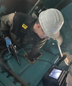
Elgeti Engineering performs on-site inspections of large industrial gearboxes with endoscopy as a standard practice. A recent case in a wind energy converter clearly demonstrates the importance of both regular inspections and correct maintenance procedures. A damaged bearing was found less than a year after the last oil change in a gearbox that had been operating without issue for almost two decades.
Our analysis showed that it was the oil change, performed improperly, that led to the development of white etching cracks and thus the failure of the bearing. This diagnosis has grave consequences for the remaining bearings in the gearbox as well as those in any other gearboxes serviced in the same manner.
Find all of our articles here.
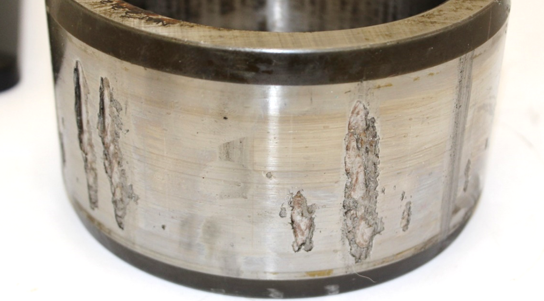
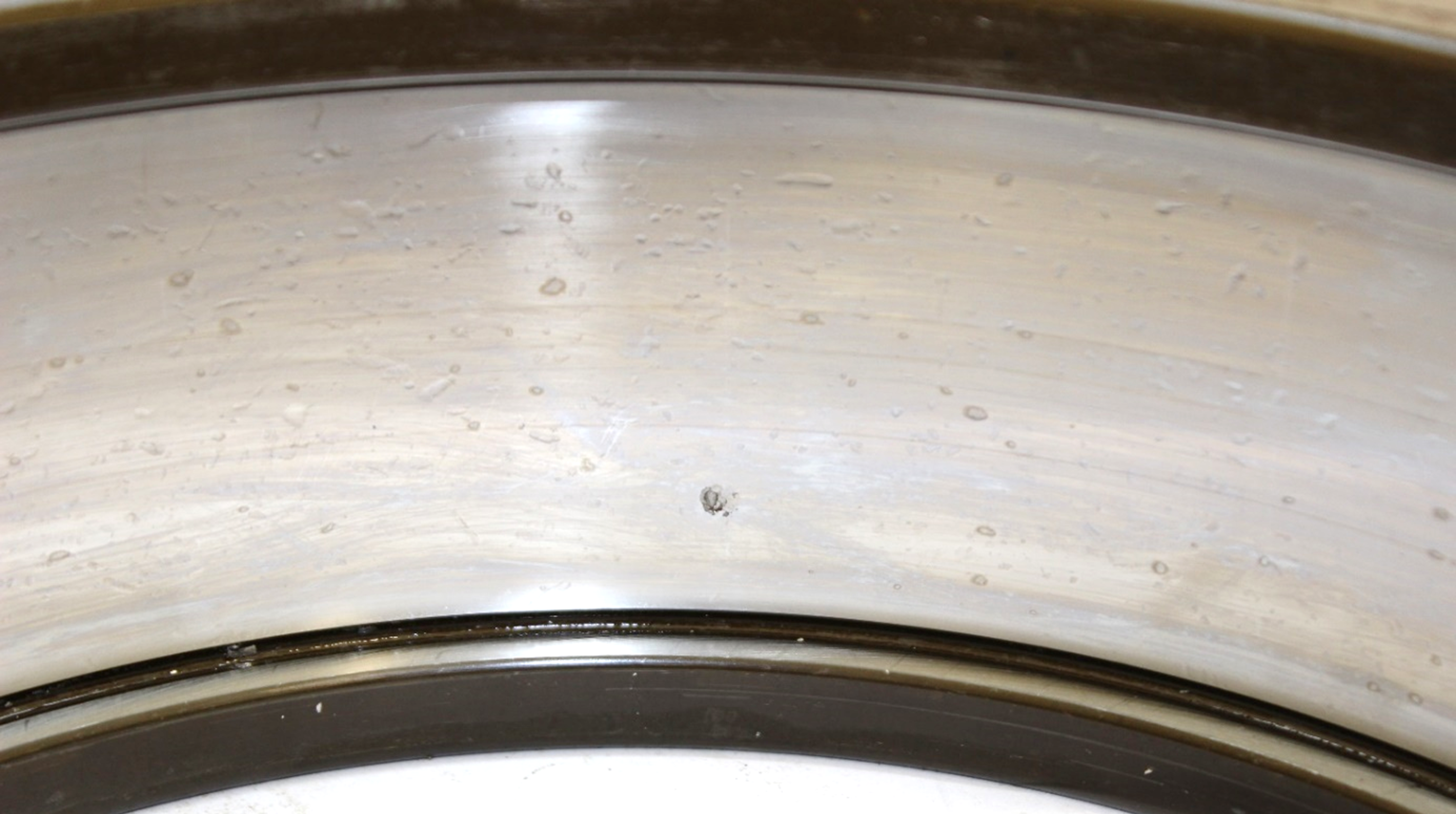
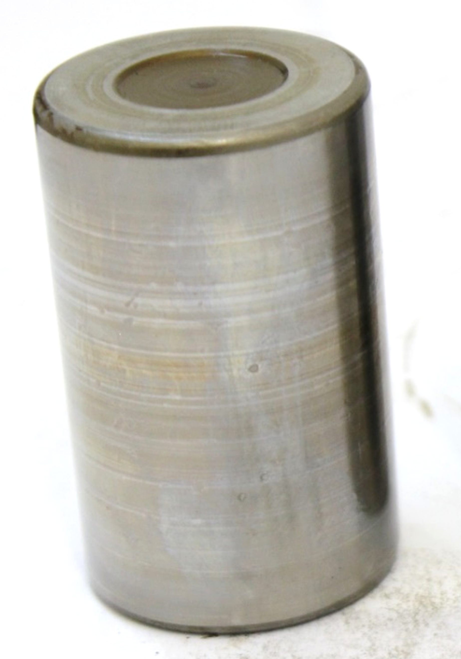
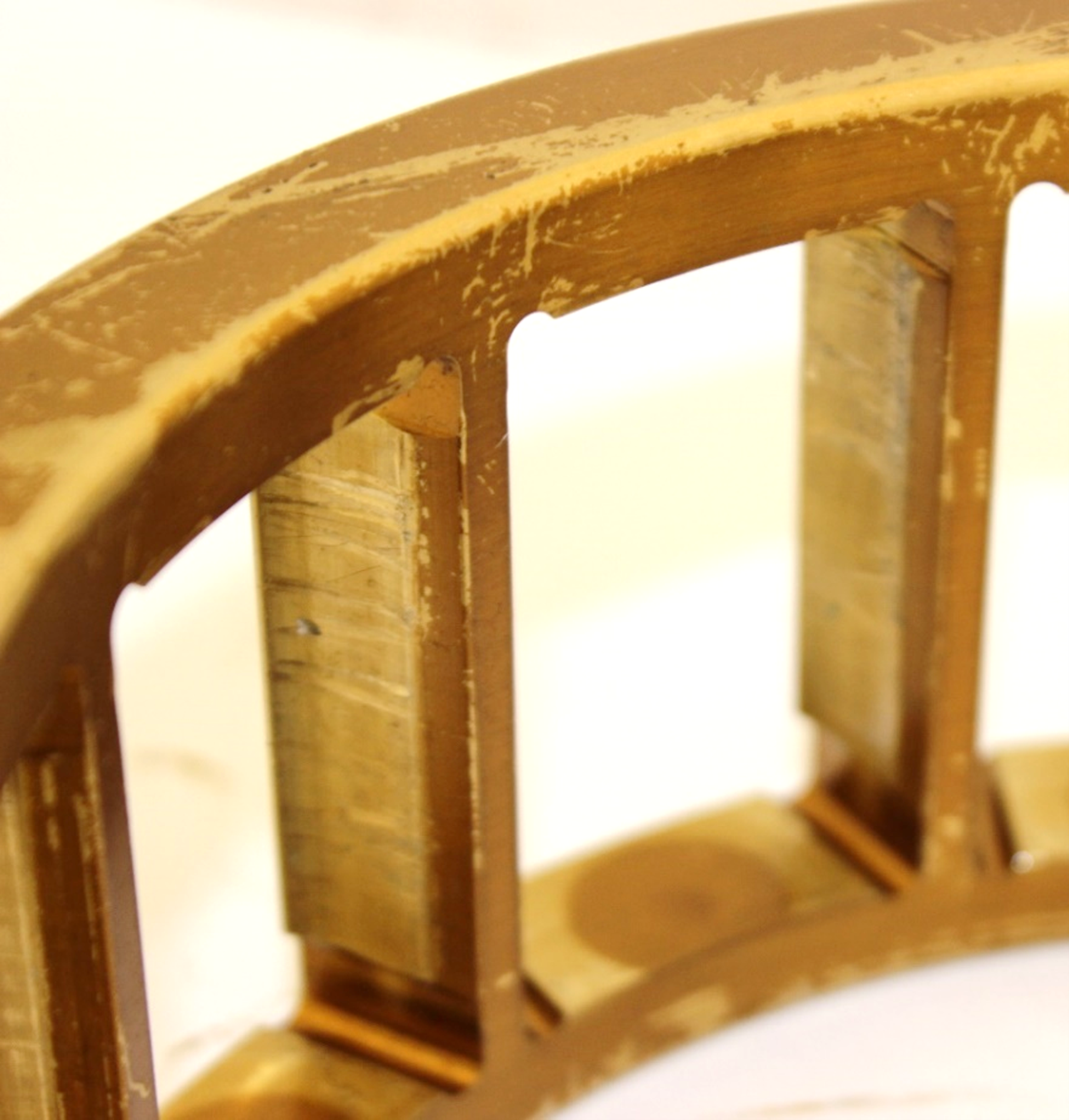
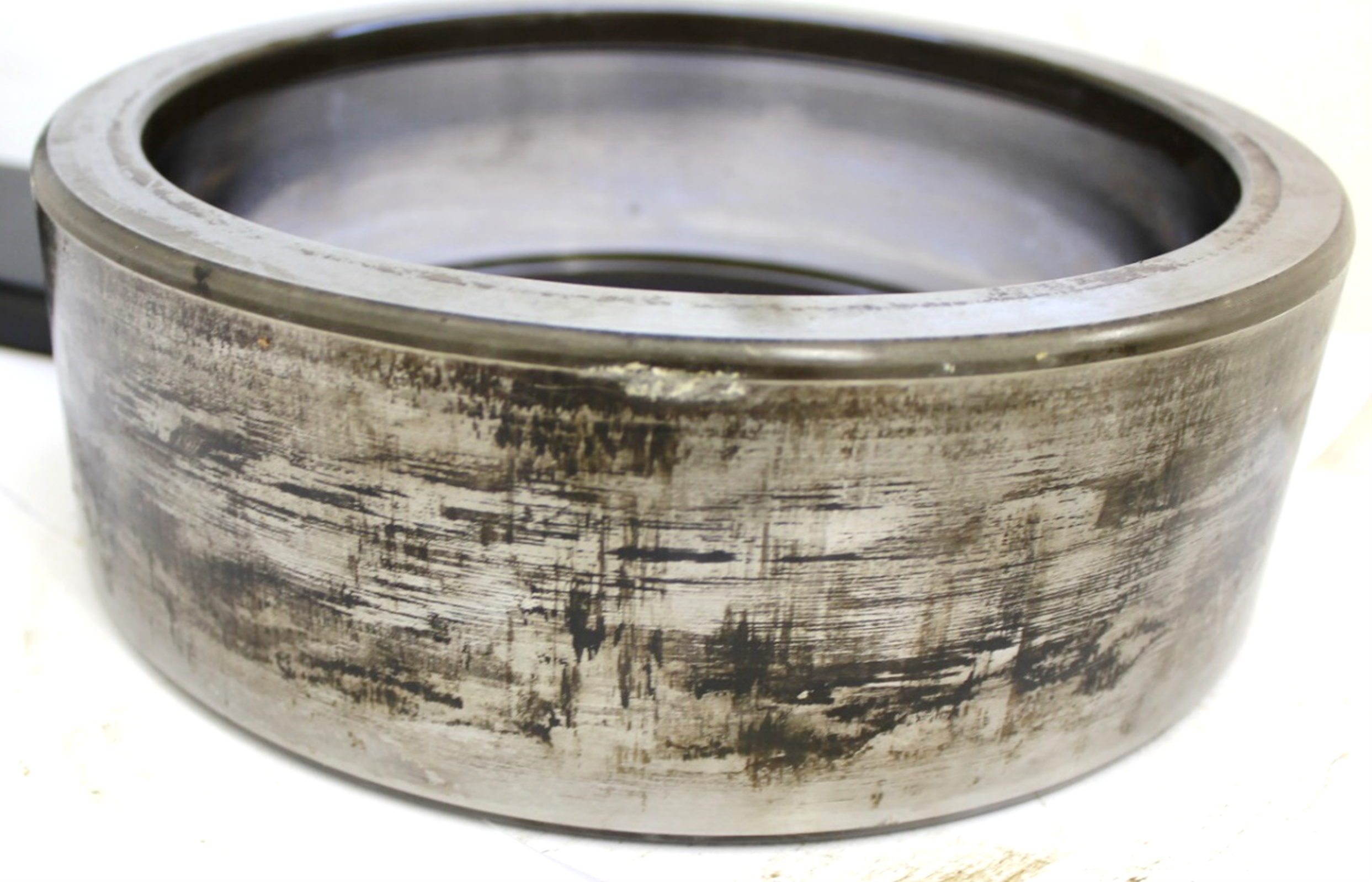
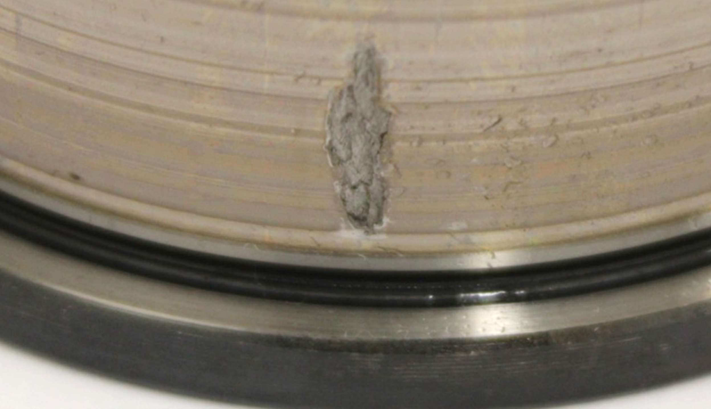
After documenting its condition upon arrival, the bearing was disassembled and cleaned. Multiple damages were present on the inner ring (Figure 2) while the outer ring had only a single point of damage (Figure 3). Both raceways as well as the rollers show signs of rolled over particles that can be considered as secondary damages to the inner ring (Figure 4). The presence of harder particles is also evident in the wear visible on the cage (Figure 5). Frictional wear is visible on both bearing seats, more pronouncedly on the outer ring (Figure 6), but this is unremarkable given the fits typically employed in the application. Aside from oil deposits, there are no further significant findings.
Since the marks observed on the other components are clearly secondary, the focus will subsequently be on interpreting the damage to the inner ring.
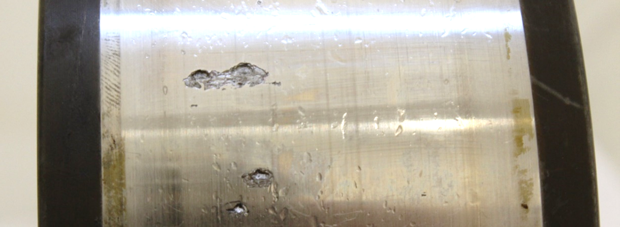
The fundamental truth about rolling element bearings is that their lifetimes are finite. In principle, a fatigue damage can occur at any time – especially when the bearing has been in use for many years, as this one has. Fatigue damage is characterized by spalling on the raceway that first spreads across the width and then propagates around the circumference. The damaged surface has a regular, flaked appearance as in Figure 7. This image shows damage due to fatigue on a comparable bearing that was run under high load until failure on one of Elgeti Engineering’s test rigs.
The extent and depth of the flaking is dependent upon the applied load. The rollers and rings flatten elastically under load to form a rectangular contact area. While the length is equal to the raceway width and remains constant, the width of the contact area increases with higher loads. The area of greatest material stress occurs at a depth equal to approximately 35% the contact width. Over time, subsurface cracks develop that run parallel to the surface. Material eventually flakes off, leaving a characteristic damage profile.
Typically, fatigue damages only have a few sources – frequently only one – although the damage can then spread quickly. This is because the initial damage leads to a weakening of the surrounding material while the rest of the component remains intact.
If multiple damages occur within a short period of time in one component, as they have in this bearing, two conditions must be fulfilled. First, the load must be fairly low so that the progression of damage is slowed and more cracks are able to develop and reach the surface. Second, the component must be compromised in some other way so that there are multiple weak points in the material where cracks can begin to develop. These weak points must exert a greater influence than the cracks themselves. Three potential causes can be considered:
Neither of the first two options apply to the bearing in question. There are no identifiable unrelated damages on the surface and if the material quality were at fault, one would not have expected the bearing to have run for so many years without failure (the subsequent metallographic inspection supports this reasoning).
This leaves changes to the microstructure as the only remaining possibility. A close examination of the damaged areas shows two phenomena in superposition: rolling element fatigue that presents as fine flaking, and areas that are flatter and deeper (Figure 8). The latter fractures are characteristic of material embrittlement and it can reasonably be assumed that these areas appeared first and caused the fatigue damages. Additionally, the axial cracks emanating from some of the damaged areas (Figure 9) are also typical of material embrittlement; more specifically, these cracks frequently occur in connection with white etching cracks.
The primary suspect for the root cause of this embrittlement – and white etching cracks – is the presence of atomic hydrogen, which among other things can developed due to chemical degradation of the lubricant.

To definitively identify the underlying cause of the damages, a material sample was taken for metallographic inspection. First, the sample was polished in order to assess the cleanliness and crack network. It was then etched with 3% nitric acid in an alcoholic solution to make the microstructure visible.
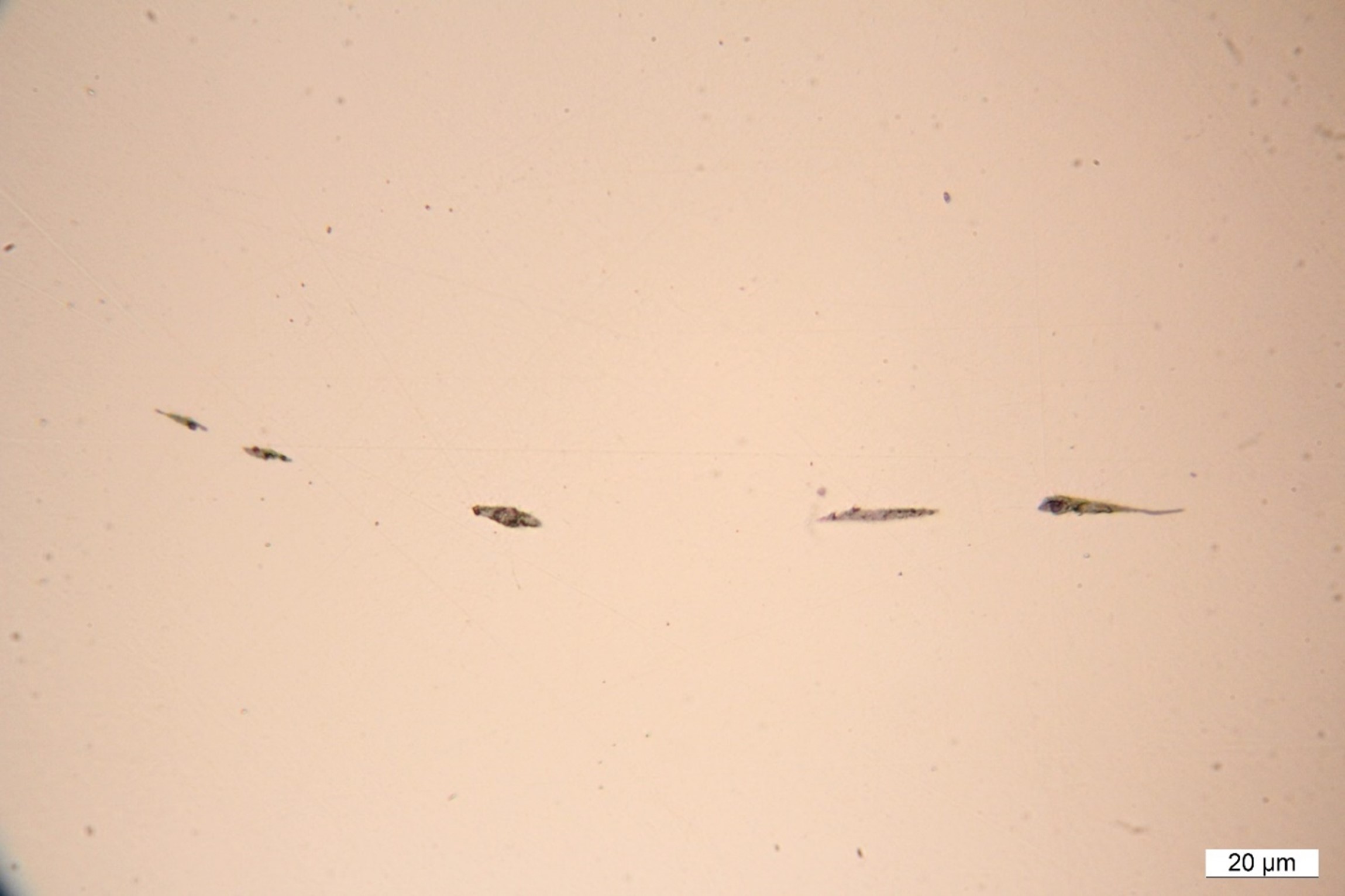
Overall, the cleanliness is good with only a few small inclusions, predominantly elongated manganese sulphide (grey) paired with oxides (black) (Figure 10). This degree of inclusions is completely normal and not of concern. The microstructure itself is very regular and shows that the bearing was made of high-quality steel and appropriately heat treated.
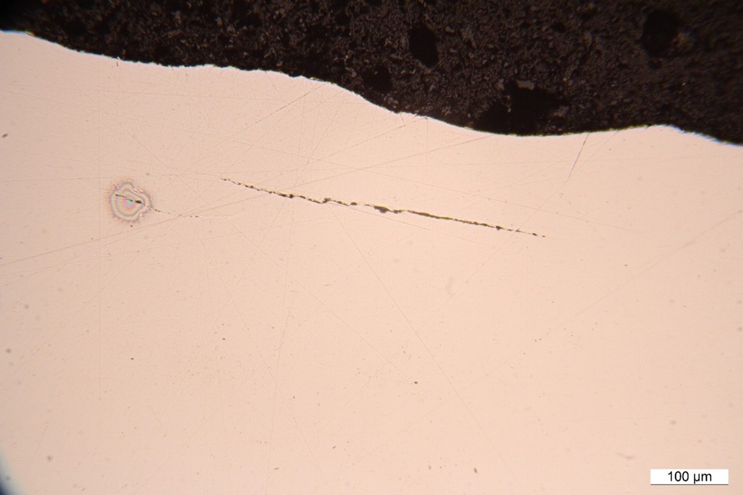
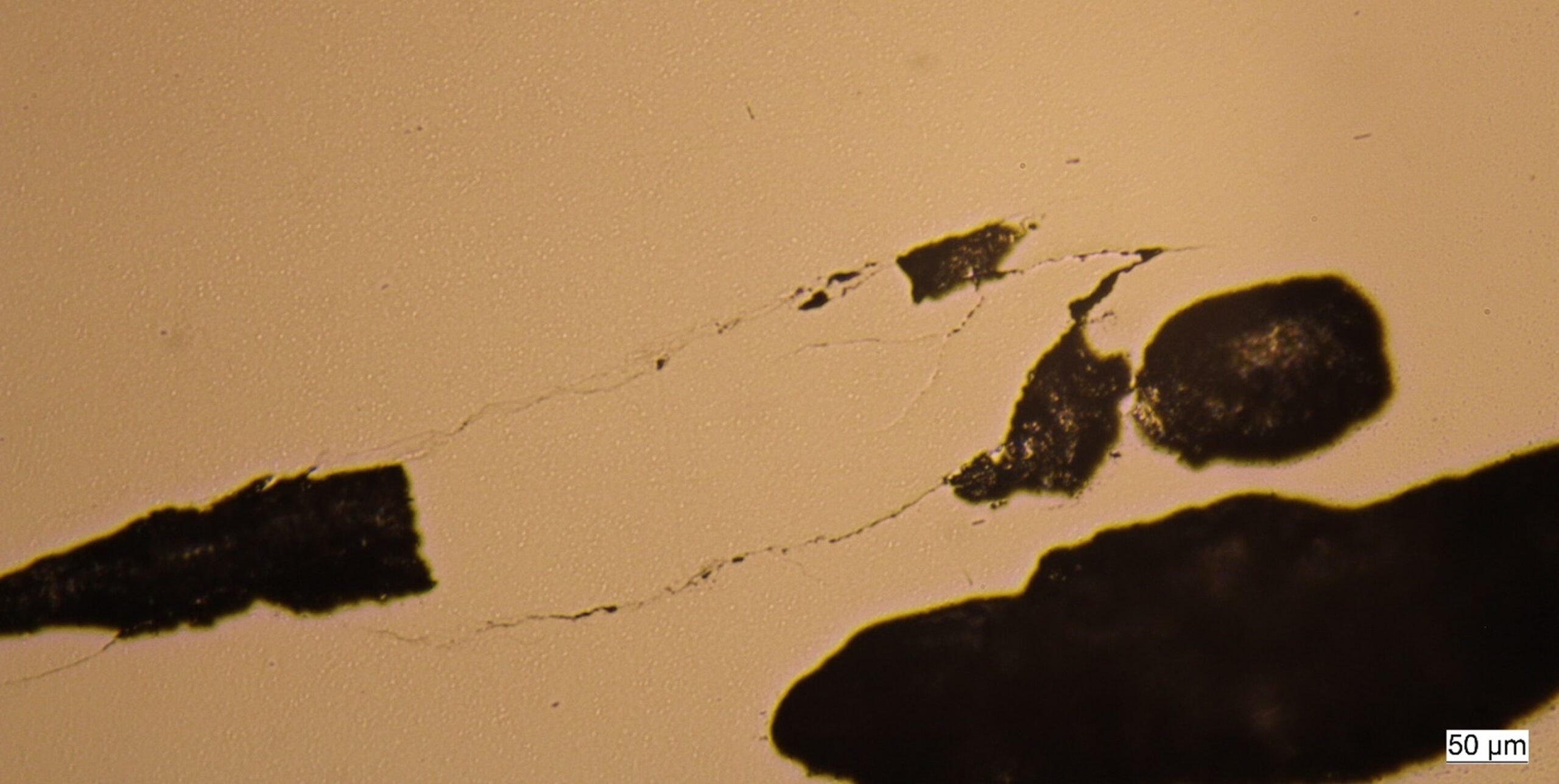
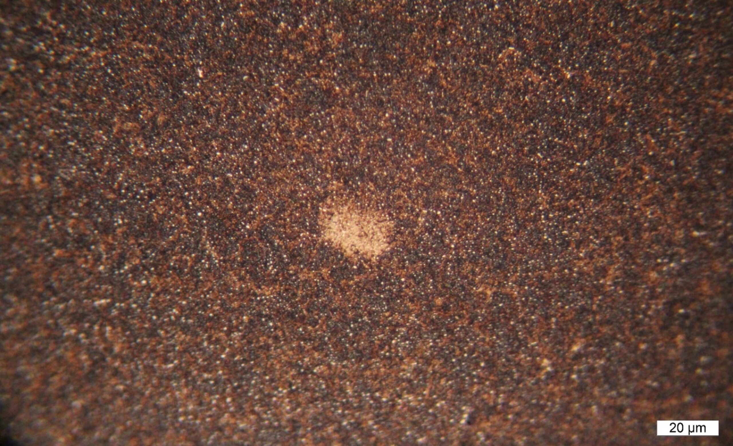
While Figure 11 shows parallel subsurface cracks typical of rolling element fatigue, Figure 12 shows a chaotic crack network that is indicative of embrittlement. Indeed, Figure 13 shows a white etching area visible as a lighter spot in the microstructure. These white etching areas are structural modifications associated with the presence of atomic hydrogen and which lead to a significant weakening of the material. When cracks develop from these areas they are called white etching cracks (Figure 14 and Figure 15).
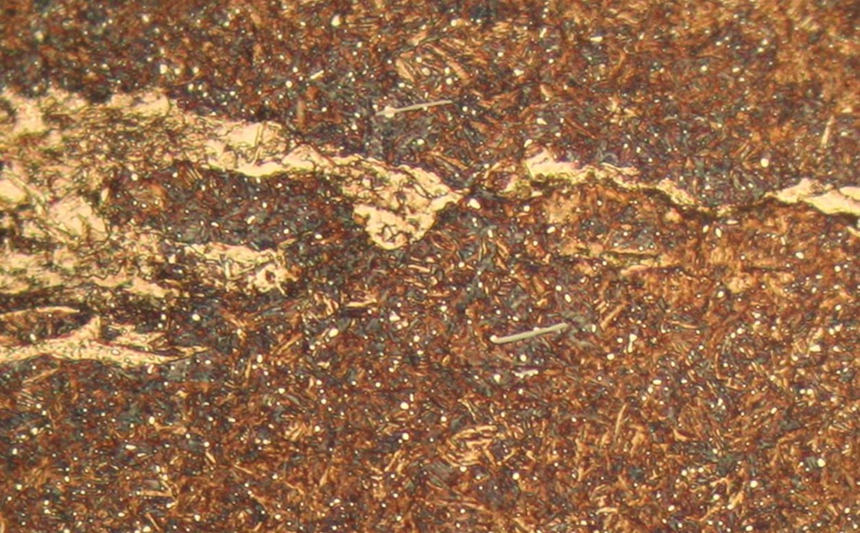
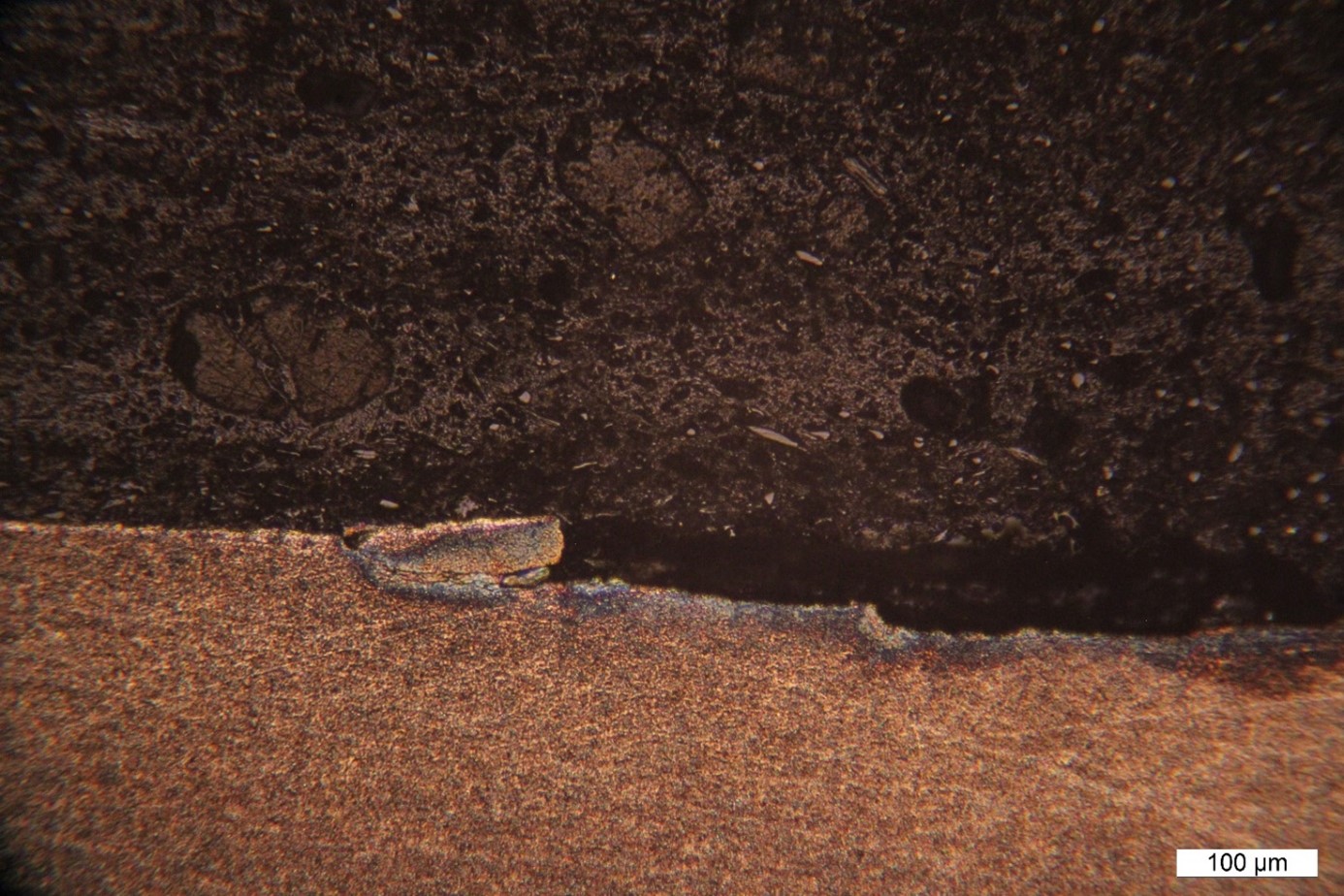
The analysis of the oil sample showed that the wear particles were within the normal range. However, the composition of the additives did not match the database entry for the lubricant. The technician expressly states that the sample is likely to be a mixture of two different lubricants.
The examined bearing failed due to damage on the inner ring caused by a superposition of rolling element fatigue and embrittlement fractures. In this case, the fatigue damages were a consequence of the cracks caused by the embrittled material.
The metallographic inspection showed that the bearing was made of high-quality material which had nevertheless developed white etching cracks. White etching cracks develop in the presence of atomic hydrogen and lead to premature failure. It is reasonable to conclude that the failure was precipitated by the presence of atomic hydrogen. Other possible damage mechanisms cannot be plausibly associated with the observed damaged; explicitly discounted is the possibility that the bearing had simply reached the end of its lifetime.
The existence of white etching cracks is closely connected to the presence of electrical currents and/or inappropriate lubricants. Electrical currents lead to an electrolytic decomposition of the lubricant and can additionally encourage the diffusion of hydrogen into the material. This phenomenon is frequently observed in assets that are not appropriately shielded. In these cases, the damages appear within a few months or years. Since the asset in question has been in operation considerably longer than that without issue, it can reasonably be assumed that such a problem was not present.
With respect to the lubricant, recent research has shown that even a single additive can cause white etching cracks to develop; such results were, for example, presented by Dr. Arnaud Ruellan et. al. (SKF Group) at the BearingWorld 2020 conference. Since white etching cracks develop quickly, it can be assumed with near certainty that running for a few months with a contaminated lubricant could cause the observed damage.
Aside from the findings of the lubricant analysis, the excessive foaming observed during the visual inspection of the gearbox demonstrates the incompatibility of the two oils, particularly the resultant failure of the foam inhibiting additives. This foaming is associated with chemical reactions that could help explain the development of hydrogen responsible for inducing the damage in the bearing.
Since the bearing failure was caused by a contaminated lubricant and the failure occurred in close proximity to an oil change during which the type of oil was altered, it is reasonable to conclude that the oil change was performed improperly. Consequently, it is essential to thoroughly flush and then relubricate the gearbox. The same applies for any other gearboxes that were serviced in the same manner.
White etching cracks can affect any and all of the bearings in the gearbox, and further damages can be expected in the coming months and years. It is therefore highly important to conduct regular inspections in order to detect these failures before they propagate and cause further damages inside the gearbox.
Finally, the maintenance procedures and training of the maintenance personnel should be investigated to determine the source of the initial error and correct it.